Comfy HDL Design Setup
This is for those who want to get into coding in an HDL but don’t know where to start, as I was a few months ago.
- The language: systemVerilog
- The simulator: Verilator
- The visualizer: GTKWave
How to code - simulate - visualize?
Code
First step is to write your design.
Simple example:
module blink (
    input clk,
    output led
    );

    assign led = clk;

    endmodule // blink
Then you write your testbench¹ to provide input to your DUT/UUT².
Simple example:
    module blink_tb;
        reg clk;
        wire led;

    blink dut (
        .clk(clk),
        .led(led)
        );

    initial clk = 0;
    always #5 clk <= ~clk;

    initial
        begin
            $display("Running testbench...");
            $dumpfile("dump.vcd");
            $dumpvars(0);
            #30_000_000;
            $display("Done: made file dump.vcd");
            $finish;
        end
    endmodule // blink_tb
Simulate
If we keep the same design and testbench as above you can use a command such as this one to compile your tb: verilator --trace --binary --build-jobs 0 -Wall blink_tb.sv -Wno-lint -timing -o cool
After that, go into the obj_dir and the run the executable.
If you added a dumpfile in your code it should now be in the same directory.
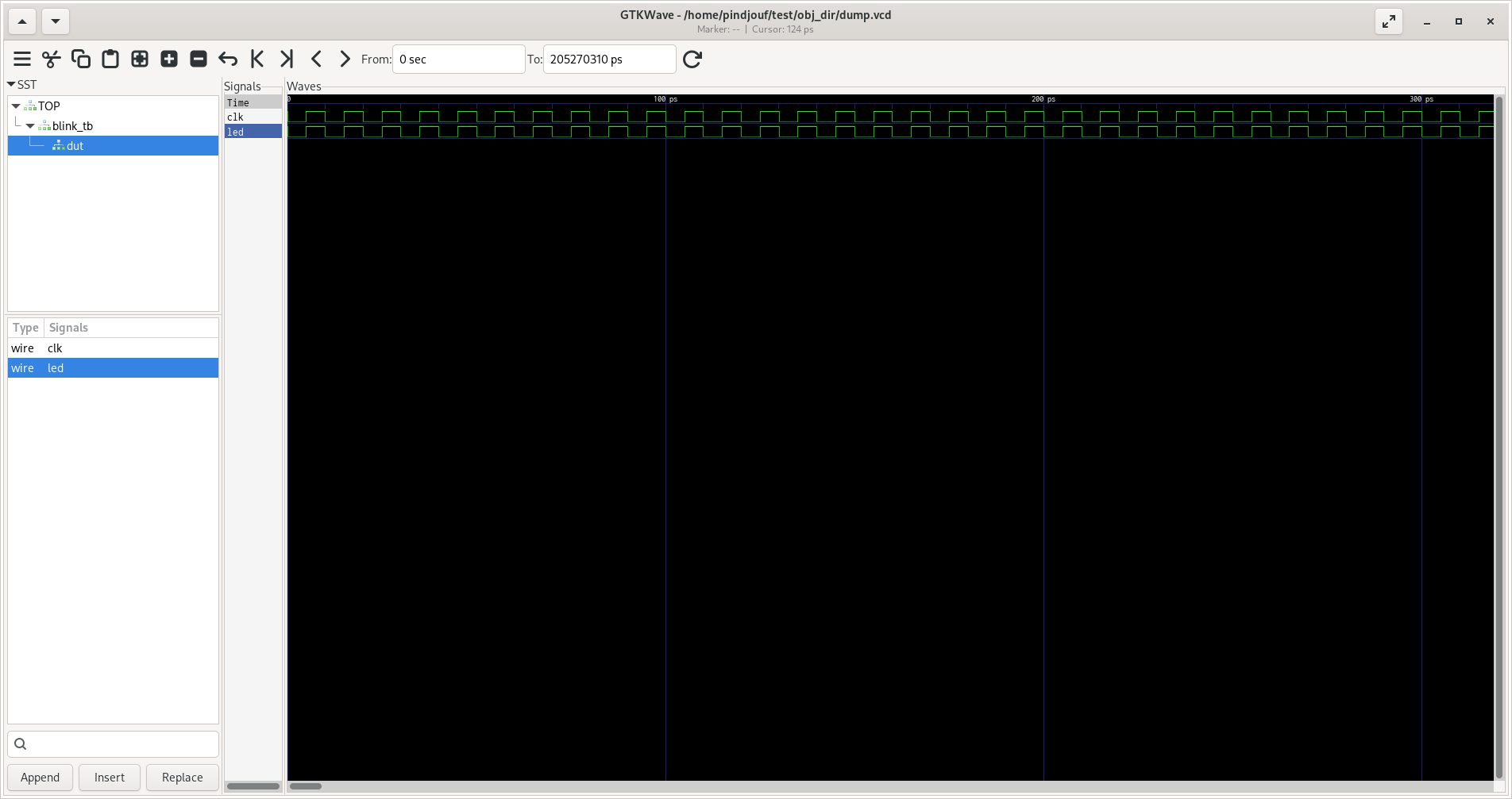
Visualize
- Go into GTKWave.
- Make new tab with your .vcd file.
- Select all your signals in the left column.
- Analyze and enjoy! :D
Glossary
- The function of a testbench is to apply stimulus (inputs) to the DUT/UUT, and report the outputs in a readable and user-friendly format.
- Device Under Test | Unit Under Test.