Day 1 of making a UART 𓇲 I made a SIPO shift register
I don’t think I’ve mentioned this on here before but, I’m loosely following the fromthetransistor course here and there when I have the time and energy.
Obviously, I’ve made this work correctly so I know how to do it. But I wanted to write this down to see how well I could articulate the concepts I’ve learned.
The first place I went to was wikipedia and I found this exact diagram.
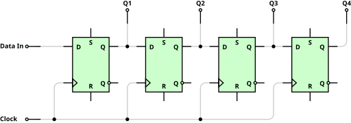
It made the concept of a shift register much clearer and gave me the blueprint on what I should be working on to make it happen. The first thing this inspired me to make was a D flip flop which I learned about in this article and by doing some exercises on HDLBits. This ressource was also very helpful to my understanding of flip flops and latches.
D Flip-flop
This is the first thing I had to implement because it’s the main piece of the puzzle. The flip flop is what holds the data in transit, it’s a very basic form of memory. Here’s my dff module in verilog:
module dff (
    input d,
    input clk,
    input reg reset,
    output reg q
);

always @ (posedge clk or negedge clk) begin
    if (reset) begin
        q <= 1'b0;
    end else begin
        q <= d;
    end
end

endmodule
You can see how this closely reflects the flip flops in the previous image, the only thing that’s missing here is the set input, but it’s not something that I felt was necessary for our use case so I simply decided not to include it. As you can see it’s pretty simple, the output q updates to match the input d at posedge or negedge of clk, unless reset is active high, in which case q is set to 0.
SIPO
As the name states (Serial-in parallel-out) the goal of this register is to take serial data and convert it to parallel. Meaning, it will come in bit-by-bit and come out as a data block.
To hold values, I implemented a simple wire called hold_value and used ternary operators on the flip flop instantiations’ input d pins, that serves as a multiplexer that choses between shifting in new data or recycling its own output.
Here’s my SIPO module in verilog:
module sipoUnit #(parameter WIDTH = 8) (
    input wire data_in,
    input wire hold_value,
    input wire reset,
    input wire clk,
    output reg [WIDTH-1:0] q
);

    dff dff0 (
        .d(hold_value ? q[0] : data_in),
        .reset(reset),
        .clk(clk),
        .q(q[0])
        );

    generate
        for (genvar i = 0; i < WIDTH-1; i++) begin
            dff dff_inst (
                .d(hold_value ? q[i+1] : q[i]),
                .reset(reset),
                .clk(clk),
                .q(q[i+1])
            );
        end
    endgenerate

endmodule
I feel that there is nothing else to add. Really, the SIPO register seemed daunting to me at first but when I started breaking the pieces down it became clearer what the next implementation should be.
If there’s anything that’s unclear, or you need clarification on any of the decisions made in this code, feel free to contact me on twitter: @pindjouf.