Day 2 of making a UART 𓇲 I made a PISO shift register
Like yesterday, the first place I went to was wikipedia to find the following diagram:
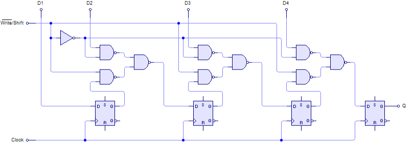
As you can see it’s very similar to the SIPO shift register I made yesterday but the main difference is that here we’re loading the data straight away into each flip flop and only then does the shifting happen.
D Flip-flop
I tried to reuse the same module but since we needed the input to be loaded straight away from a data block it became quite awkward trying to make it work.
So I reformatted a lot of it and didn’t even use an instance of that specific module, I simply made an internal one with this:
reg [WIDTH-1:0] shift_reg;So instead of treating each flip flop as an individual register, I just made a vector and each item in there serves as a flip flop. Now to load the data I used a counter like this:
if (shift_counter == 0) begin
    shift_reg <= data;
As you can see I only load a new data block when the counter is at 0, I tried to use the state of the shift register itself as a condition but I had some trouble making it work. (I blame my lack of knowledge on how to test properly)
I also found out that there is a shift operator in verilog :D which made this way simpler than I thought it would be. I probably should change the SIPO shift register to follow this format as well. We’ll see if I stop being lazy.
Shifting data
So here’s how I implemented the main part of this register, the shifting!
q <= shift_reg[0];
shift_reg <= shift_reg >> 1;
It can really be that simple when you know all the features of a language and stop learning exclusively from trial and error!
What these two lines are doing is simply
- make
qthe LSB of our shift register i.e. the item positioned at index 0. - shift the register to the right by one bit.
So as you can see it, since the bit at index 0 changes on every rising edge of the clock because we’re shifting it out, we always get the previous one in line until the register is totally empty. That’s when we reset and bring everything back to zero. (Except the clk obviously)
if (reset) begin
    shift_reg <= 0;
    // hold_reg <= 0;
    shift_counter <= 0;
    q <= 1'b0;
As you can see in the previous codeblock I have a hold register in the works, I plan on using it to stop the shifting and keep the same value in the register. Or eventually use it as a “spare” register that can hold data while the main one works on another block.
I think that’s all for this one, I’ll leave you with the full module in verilog:
`timescale 1ns/1ps

module pisoUnit #(parameter WIDTH = 8) (
    input clk,
    input [WIDTH-1:0] data,
    input reset,
    output reg q
);

    reg [WIDTH-1:0] shift_reg;
    // reg [WIDTH-1:0] hold_reg;
    reg [3:0] shift_counter;

    always @ (posedge clk or posedge reset) begin
        if (reset) begin
            shift_reg <= 0;
            // hold_reg <= 0;
            shift_counter <= 0;
            q <= 1'b0;
        end else begin
            shift_counter <= shift_counter + 1;
            if (shift_counter == 0) begin
                shift_reg <= data;
            end else begin
                q <= shift_reg[0];
                shift_reg <= shift_reg >> 1;
            end
        end
    end

endmodule
If you’re someone with more experience and/or know how to improve some of the things I’ve done, or if you simply have questions on why I took certain decisions in this block of code, feel free to reach out to me via twitter: @pindjouf. Don’t forget that you can always follow the progress of this project on my GitHub repo.